English
3000/5000/6000 VA
On this page you find the APC Smart-UPS X 3000VA manual. Please read the instructions in this operator manual carefully before using the product. If you have any questions about your that are not answered in the manual, please share your question in the troubleshooting section on the buttom of this page. Smart-UPS ® RT. 3000/5000/6000 VA 200-240 Vac. Tower/Rack Mount 3U. Uninterruptible Power Supply. 2009 APC by Schneider Electric. APC, the APC logo, Smart-UPS and PowerChute are owned by Schneider Electric Industries S.A.S., American Power Conversion Corporation, or affiliated companies.
Tower/Rack Mount 3U
Uninterruptible Power Supply
2009 APC by Schneider Electric. APC, the APC logo,
Introduction

The APC by Schneider Electric
INSTALLATION
Read the Safety Guide before installing the UPS.
Unpacking
Inspect the UPS upon receipt. Notify the carrier and dealer if there is damage. The packaging is recyclable; save it for reuse or dispose of it properly.
Check the package contents:
UPS (with battery modules disconnected)
Front bezel
Literature kit containing:
Apc Smart Ups 3000 Rackmount
Product documentation, Safety Guide, and Warranty Information
Software CD
Serial cable
3000 VA XLI models: three output power cords, two input power cords
5000/6000 VA XLI models: six output power cords, Network Management Card documentation
Specifications
TEMPERATURE | This unit is designed for indoor use | |||
OPERATING | 32° to 104° F (0° to 40° C) | only. Select a location sturdy enough to | ||
STORAGE | 5° to 113° F | handle the weight. | ||
battery every six months | Do not operate the UPS where there is | |||
MAXIMUM | excessive dust or the temperature and | |||
ELEVATION | humidity are outside the specified limits. | |||
OPERATING | 10,000 ft (3,000 m) | Ensure that the air vents on the front | ||
STORAGE | 50,000 ft (15,240 m) | and rear of the UPS are not blocked. | ||
HUMIDITY | 0 to 95% relative humidity | |||
WEIGHT | ||||
UPS | 120 lbs (55 kg) | |||
UPS WITH | 140 lbs (64 kg) | |||
PACKAGING | ||||
. | 1 | |||
Wiring and Connecting the UPS
5000/6000 VA XLI MODELSONLY: HARDWIRINGINSTRUCTIONS
•Wiring must be performed by a qualified electrician.
•Install a high magnetic 30/32 A utility circuit breaker.
•Adhere to all national and local electrical codes.
•Use #10 AWG gauge (5 mm2) wire.

1.Switch the utility circuit breaker OFF.
2.Remove the input access panel.
3.Remove circular knockout.
Apc 1500 Smart Ups Manual
4.Run #10 AWG gauge (5 mm2) wire through the access panel, and connect the wires to the terminal block (green: ground, brown: hot, blue: neutral). Use an appropriate strain relief (not included).
5.Switch the utility circuit breaker ON.
6.Check line voltages.
7.Replace the access panel.
CONNECTING THEBATTERY MODULES ANDATTACHING THEFRONTBEZEL

.
3
BASICCONNECTORS
Power management software and interface kits can be used with the UPS. | |||||||
serial com | Use only interface kits supplied or approved by APC. | ||||||
Any other serial interface cable will be incompatible with the UPS | |||||||
connector. | |||||||
Manual bypass enables the user to manually put connected equipment into | |||||||
bypass mode. | |||||||
normal bypass | |||||||
Emergency Power Off terminal allows the user to connect the UPS to the | |||||||
central EPO system. | |||||||
EPO terminal | |||||||
The UPS features a transient voltage | |||||||
connecting the ground lead on surge suppression devices such as telephone | |||||||
TVSS screw | and network line protectors. | ||||||
When connecting grounding cable, disconnect the unit from the utility | |||||||
power outlet. | |||||||
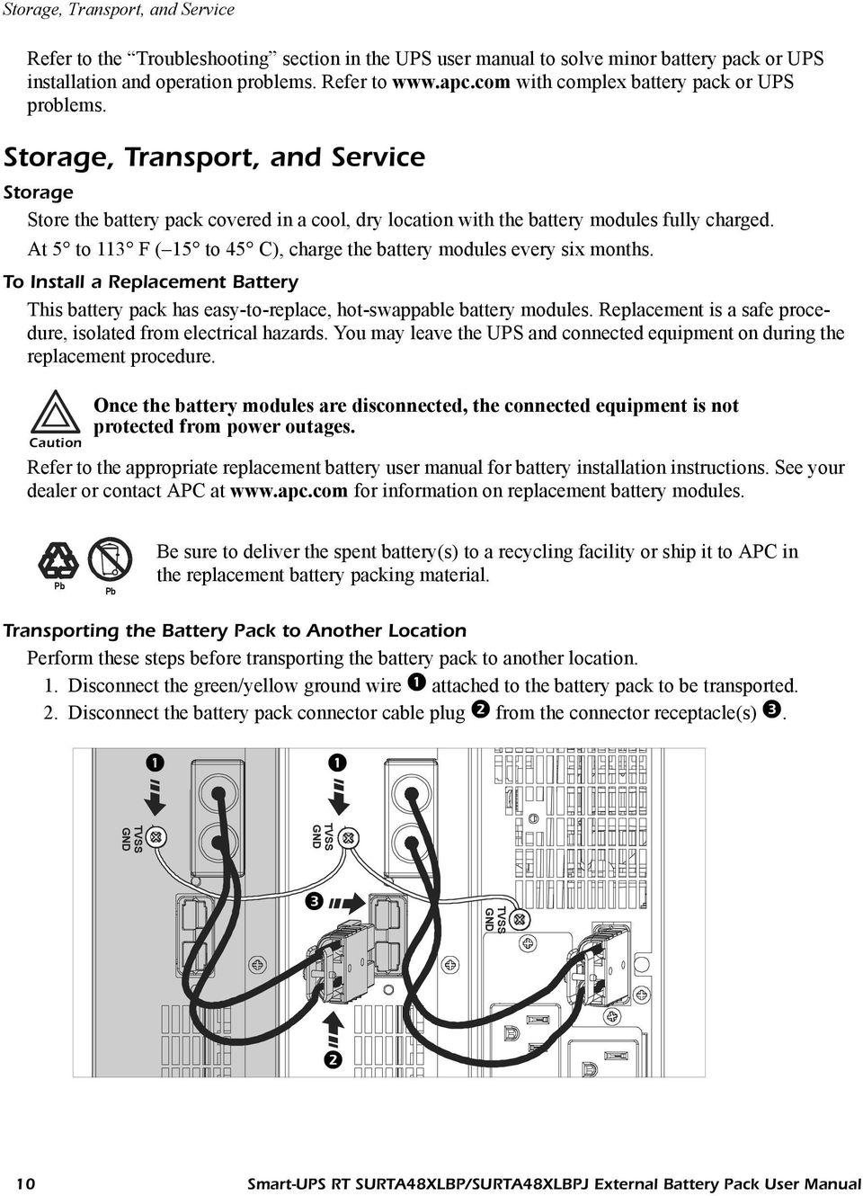
Optional external battery packs provide extended runtime during power | |||||||
outages. These units support up to ten external battery packs. | |||||||
external battery | |||||||
See the APC Web site, www.apc.com for the information on the external | |||||||
pack connector | battery pack, SURT192XLBP. | ||||||
5000/6000 VA | |||||||
XLI models | |||||||
output circuit breakers
3000/5000/6000 VA XLJ/XLT/XLTW models
output circuit breaker
CONNECTINGEQUIPMENT ANDPOWER TO THEUPS
1.Connect equipment to the UPS (cables not included for XLJ/XLT/XLTW models).
2.Avoid using extension cords.
•3000 VA XLJ/XLT/XLTW/XLI and 5000/6000 VA XLJ/XLT/XLTW models: Using a power cord, plug the UPS into a
•5000/6000 VA XLJ and 6000 VA XLT models: To draw full power from the UPS have a qualified electrician cut off the input plug and hardwire the UPS to the appropriate power panel.
3.Turn on all connected equipment. To use the UPS as a master ON/OFF switch, ensure all connected equipment is switched ON. The equipment will not be powered until the UPS is turned on.
4.To power up the UPS press the button on the front panel.
•The UPS battery charges when it is connected to utility power. The battery charges to 90% capacity during the first three hours of normal operation. Do not expect full battery run capability during this initial charge period.
5.For additional computer system security, install PowerChute® Business Edition
OPTIONS
Refer to the APC Web site, www.apc.com for available accessories.
Apc Smart Ups 3000va Manual
External Battery Pack SURT192XLBP
Apc Smart Ups 3000 Specs
Rail Kit SURTRK2
Isolation Transformer
Service Bypass Panel
.
5
OPERATION
Load | Battery Charge | |||||
Indicator | Description | ||||
Online | The Online LED illuminates when the UPS is drawing utility power and performing | ||||
double conversion to supply power to connected equipment. | |||||
On Battery | The UPS is supplying battery power to the connected equipment. | ||||
Bypass | The Bypass LED illuminates indicating that the UPS is in bypass mode. Utility | ||||
power is sent directly to connected equipment during bypass mode operation. | |||||
Bypass mode operation is the result of an internal UPS fault, an overload condition | |||||
or a user initiated command either through an accessory or the manual bypass | |||||
switch. Battery operation is not available while the UPS is in bypass mode. Refer to | |||||
Troubleshooting in this manual. | |||||
Fault | The UPS detects an internal fault. | ||||
Refer to Troubleshooting in this manual. | |||||
Overload | An overload condition exists. See Troubleshooting. | ||||
Replace | The battery is disconnected or must be replaced. See Troubleshooting. | ||||
Battery | |||||
Feature | Function | ||||
Power On | Press this button to turn on the UPS. (See below for additional capabilities.) | ||||
Power Off | Press this button to turn off the UPS. | ||||
Feature | Function | ||||||||||
Cold Start | When there is no utility power and the UPS is off, press and hold the | button to | |||||||||
power up the UPS and connected equipment. | |||||||||||
The UPS will emit two beeps. During the second beep, release the button. | |||||||||||
Automatic: The UPS performs a | |||||||||||
two weeks thereafter (by default). During the | |||||||||||
connected equipment on battery. | |||||||||||
Manual: Press and hold the | button for a few seconds to initiate the | ||||||||||
Diagnostic Utility Voltage | The UPS has a diagnostic feature that displays the utility voltage. Plug | ||||||||||
the UPS into the normal utility power. | |||||||||||
The UPS starts a | |||||||||||
does not affect the voltage display. | |||||||||||
Press and hold the | button to view the utility voltage bar graph | ||||||||||
display. After a few seconds the | display | ||||||||||
on the right of the front panel shows the utility input voltage. | |||||||||||
Refer to the figure at left for the voltage reading (values are not listed | |||||||||||
on the UPS). | |||||||||||
The display indicates the voltage is between the displayed value on the | |||||||||||
list and the next higher value. | |||||||||||
On Battery Operation
The UPS switches to battery operation automatically if the utility power fails. While running on battery, an alarm beeps four times every 30 seconds.
Press the button to silence this alarm. If the utility power does not return, the UPS continues to supply power to the connected equipment until the battery is fully discharged.
When 2 minutes of run time remain the UPS emits a continuous beeping. If PowerChute is not being used, files must be manually saved and the computer must be turned off before the UPS fully discharges the battery.
The UPS battery life differs based on usage and environment. Refer to www.apc.com, for on battery runtimes.
.
Apc Smart Ups 1000 Manual
7
USERCONFIGURABLEITEMS
NOTE: SETTINGS ARE MADE THROUGH SUPPLIEDPOWERCHUTE SOFTWARE OPTIONALSMARTSLOT ACCESSORY CARDS ORTERMINALMODE.
Apc Smart Ups 3000 User Manual
FUNCTION | FACTORY | USERSELECTABLE | DESCRIPTION |
DEFAULT | CHOICES | ||
Automatic | Every 14 days | Every 7 days(168 hours), | Set the interval at which the |
(336 hours) | 14 days (336 hours) | UPS will execute a | |
On Startup Only, | |||
No | |||
UPS ID | UPS_IDEN | Up to eight characters to | Uniquely identify the UPS, (i.e. |
define the UPS | server name or location) for | ||
network management purposes. | |||
Date of Last Battery | Manufacture Date | Date of | Reset this date when you replace |
Replacement | Battery Replacement | the battery modules. | |
mm/dd/yy | |||
Minimum Capacity | 0 percent | 0, 15, 25, 35, 50, 60, 75, | Following a |
Before Return from | 90 percent | shutdown, the battery modules | |
Shutdown | will be charged to the specified | ||
percentage before powering | |||
connected equipment. | |||
Alarm Delay After | 5 second delay | 5 or 30 second delay | Mute ongoing alarms or disable |
Line Failure | At Low Battery | all alarms permanently. | |
Never | |||
Shutdown Delay | 20 seconds | 0, 20, 60, 120, 240, 480, | Set the interval between the time |
720, 960 seconds | when the UPS receives a | ||
shutdown command and the | |||
actual shutdown. | |||
Duration of | 2 minutes | 2, 5, 7, 10, 12, 15, 18, | The low battery warning beeps |
Low Battery Warning. | PowerChute | 20 minutes | are continuous when two |
software provides | minutes of run time remain. | ||
automatic, | Change the warning interval | ||
unattended | default to a higher setting if the | ||
shutdown when | operating system requires a | ||
approximately 2 | longer interval for shutdown. | ||
minutes of battery | |||
operated runtime | |||
remains. | |||
Synchronized | 0 seconds | 0, 20, 60, 120, 240, 480, | The UPS will wait the specified |
Delay | 720, 960 seconds | time after the return of utility | |
power before | |||
branch circuit overload). | |||
High Bypass Point | +10% of | +5%, +10%, +15%, | Maximum voltage that the UPS |
output voltage | +20% | will pass to connected | |
setting | equipment during internal | ||
bypass operation. |